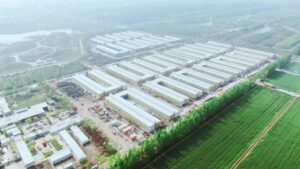
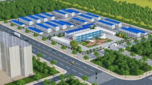
Portal frame steel structures—characterized by rigidly connected columns and rafters, often used for industrial warehouses, workshops, and large-span buildings—are highly sensitive to wind force. Wind exerts lateral pressure, uplift/suction, overturning moment, racking, and vibration that directly dominate the design of portal frames, including member sizing, connection details, bracing layout, and foundation design. Below is a detailed breakdown, plus a simplified wind load calculation and technical summary for practical application.
1. Key Wind Actions on Portal Frame Steel Structures
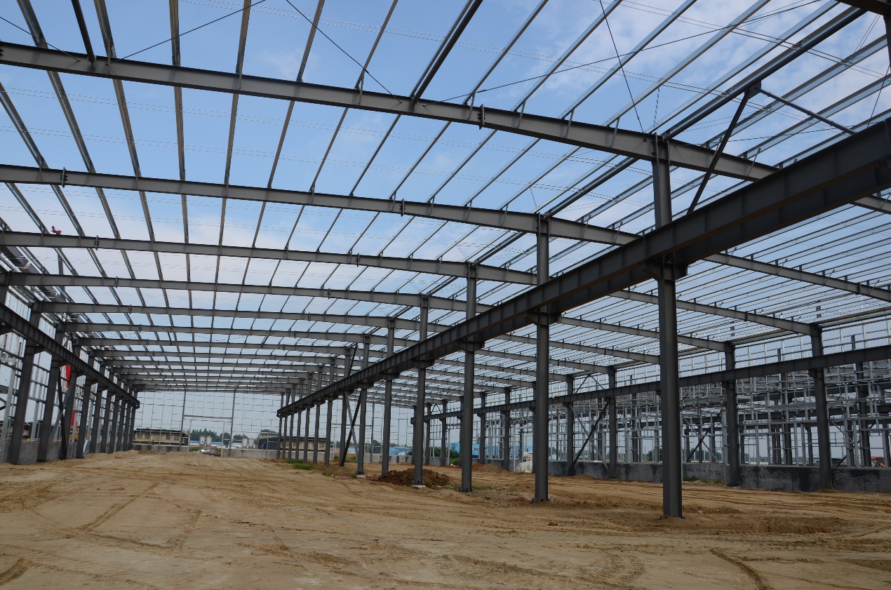
Compared to general steel structures, portal frames have unique structural features (large span, low height in most cases, open interior) that make wind effects more prominent, especially on the roof and frame joints. The main wind actions include:
- Lateral Horizontal Force: Pushes against the side walls and portal frames, causing shear and bending in columns and rafters. This is the primary force leading to frame racking (distortion) if bracing is insufficient.
- Roof Uplift/Suction: The most critical wind action for portal frames. Wind flows over the roof, creating negative pressure (suction) that pulls the roof panels, purlins, and rafters upward. Corners, eaves, and ridge lines of the roof are subject to the highest suction, risking panel detachment or rafter deformation.
- Overturning Moment: Uneven lateral force and uplift create a tipping moment on the entire portal frame system, especially for single-span or asymmetric portal frames. This places significant tension on the anchor bolts and requires the foundation to resist overturning.
- Internal Pressure: Openings (e.g., large overhead doors, windows) in portal frame buildings cause internal air pressure to change with wind, amplifying uplift and lateral forces on the frame and cladding.
- Vibration & Fatigue: Repeated wind gusts induce cyclic loading on the portal frame members and connections, leading to long-term fatigue, especially in high-wind zones or structures with flexible frames.
2. Direct Effects of Wind Force on Portal Frame Steel Design
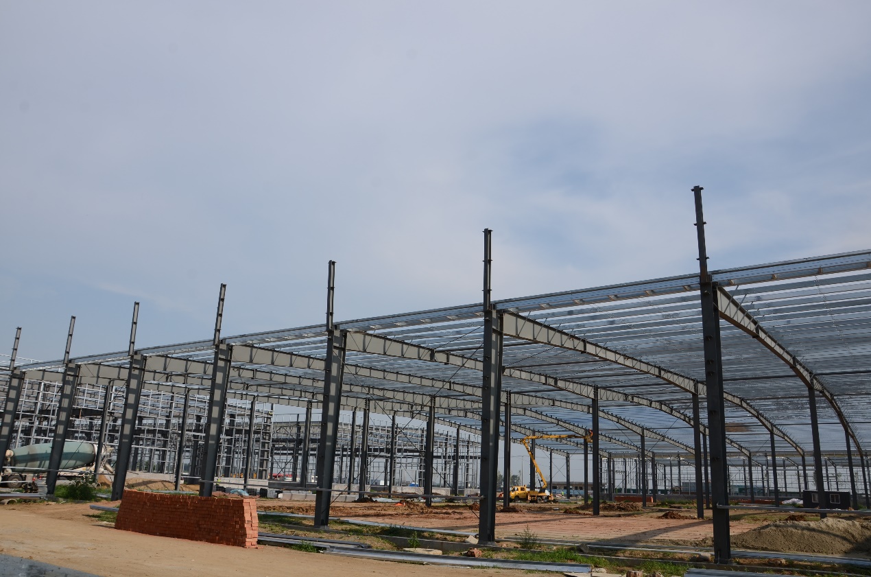
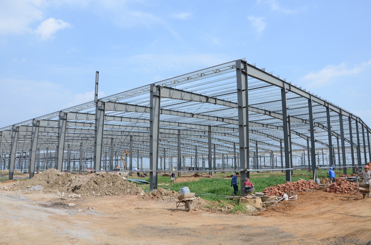
(1) Portal Frame Member Sizing (Columns & Rafters)
Portal frame columns and rafters are the primary load-bearing components, and their size and section type are directly determined by wind forces:
- Column Design: Columns must resist lateral shear and bending from wind, as well as axial forces from gravity and uplift. Higher wind speeds require thicker steel sections (e.g., H-sections, box sections) with larger moment of inertia to prevent buckling and excessive deflection.
- Rafter Design: Rafters bear the brunt of wind suction, requiring sufficient tensile and bending capacity. Low-slope roofs (common in portal frames) increase uplift, so rafters are often designed with deeper sections or additional reinforcement at eaves and ridges.
- Haunch Design: The haunch (the reinforced section at the column-rafter joint) is critical for resisting wind-induced moment. Wind increases the moment at this joint, so haunches are often thickened or extended to enhance rigidity.
(2) Bracing System Design (Critical for Wind Stability)
Portal frames rely heavily on bracing systems to transfer wind loads to the foundation and prevent frame distortion. Wind is the primary driver for bracing design, with two key types of bracing required:
- Lateral Bracing (X-bracing/K-bracing): Installed in the end walls or interior bays, lateral bracing resists horizontal wind forces and prevents the portal frame from racking. For large-span portal frames, multiple bracing bays are needed to distribute wind loads evenly.
- Roof Bracing (Purlin Bracing/Sag Rods): Resists roof uplift and prevents purlin rotation. Sag rods (installed between purlins) and diagonal bracing in the roof plane help transfer suction forces to the columns and foundation. Anti-uplift clips are also used to secure roof panels to purlins.
- Portal Frame Joint Bracing: The column-rafter joint (rigid connection) must be braced to prevent rotation under wind moment. Knee bracing or stiffeners are often added to stiffen this joint.
(3) Connection Design (Joints, Fasteners, Anchor Bolts)
Wind forces place high demands on the connections of portal frames, as weak connections can lead to progressive failure (e.g., roof detachment, frame collapse):
- Column-Rafter Joints: These rigid connections must resist large wind-induced moments. Welded or bolted connections are used, with weld size and bolt quantity determined by wind moment and shear. Full-penetration welds are often required for high-wind zones.
- Purlin-Rafter Connections: Subject to wind suction, these connections use high-tensile self-drilling screws or anti-uplift clips. Closer fastener spacing is required at roof edges and corners (high suction zones).
- Anchor Bolts: Critical for resisting wind uplift and overturning. Anchor bolts must be sized for tensile strength (not just gravity) and embedded deeply in the foundation to prevent pull-out. The base plate of columns is also designed to distribute wind-induced forces to the foundation.
(4) Deflection & Rigidity Control
Portal frames must limit lateral and vertical deflection to avoid damage to cladding, doors, and windows, and to ensure occupant comfort. Wind-induced lateral deflection is typically limited to H/400 to H/500 (H = height of the portal frame). Excessive deflection can cause cladding to crack or detach, and reduce the overall stability of the frame.
(5) Roof Cladding & Secondary Members
Roof cladding (e.g., standing seam panels, corrugated steel) and secondary members (purlins, girts) are directly affected by wind suction:
- Cladding Profiles: Deep, stiff profiles (e.g., standing seam) resist uplift better than lightweight, shallow profiles. Sealed cladding prevents internal pressure buildup, which amplifies wind suction.
- Purlins & Girts: Purlins are sized to resist wind suction and bending, with closer spacing in high-suction zones. Girts (wall secondary members) resist lateral wind pressure and support cladding.
(6) Foundation Design
Foundations for portal frame steel structures are designed specifically to resist wind-induced uplift and overturning, in addition to gravity loads:
- Foundation Type: Spread footings, strip footings, or pile foundations are used, depending on soil conditions and wind loads. Spread footings are common for low-rise portal frames, while pile foundations are used for high-wind zones or weak soil.
- Uplift Resistance: Foundations must have sufficient weight or embedment to counteract wind uplift. In some cases, tension piles or ground anchors are used to enhance uplift resistance.
- Overturning Stability: The foundation’s width and depth are sized to resist the overturning moment from wind, ensuring the frame remains stable.
(7) Code & Site-Specific Compliance
Wind load design for portal frames must comply with local building codes (e.g., ASCE 7, EN 1991, GB 50009), which specify:
- Basic Wind Speed: Determined by the building’s location (e.g., 90–170+ mph in the U.S., 20–30 m/s in Europe).
- Exposure Category: Open terrain (e.g., industrial areas, rural land) results in higher wind loads than urban or wooded areas.
- Building Shape: Portal frames with large spans, low slopes, or many openings require additional reinforcement to counteract wind effects.
3. Simplified Wind Load Calculation Formula (For Preliminary Portal Frame Design)
This simplified formula is suitable for preliminary sizing of portal frame members and bracing (not a replacement for full code-compliant calculations). It calculates the wind pressure (q), which is used to determine lateral and uplift forces on the portal frame.
Formula:
$$q = 0.613 \times V^2 \times K_z \times K_e \times K_d \times K_g$$
Variables Explained (Units: Metric/Imperial):
- q: Wind pressure (Pa / psf)
- V: Basic wind speed (m/s / mph) – from local code wind speed maps
- K_z: Height exposure coefficient (accounts for wind speed increase with height; e.g., 0.8 for 10m/33ft, 1.0 for 20m/66ft in open terrain – most portal frames are 5–15m tall, so K_z ranges from 0.7 to 0.95)
- K_e: Exposure category coefficient (0.8 for urban/wooded, 1.0 for open terrain, 1.2 for coastal/open water – common for portal frames in industrial areas: K_e = 1.0)
- K_d: Directionality factor (0.85–1.0; 0.9 for most portal frames, as wind from any direction affects the frame)
- K_g: Gust effect factor (1.0–1.2; 1.1 for portal frames with rigid cladding, 1.2 for flexible cladding)
Example (Portal Frame Application):
Basic wind speed V = 22 m/s (79 mph), K_z = 0.85 (12m tall portal frame), K_e = 1.0 (open industrial terrain), K_d = 0.9, K_g = 1.1
$$q = 0.613 \times 22^2 \times 0.85 \times 1.0 \times 0.9 \times 1.1 = 0.613 \times 484 \times 0.8415 ≈ 254 Pa$$ (≈ 5.31 psf)
Note: Final design must use full code calculations (e.g., ASCE 7-16, EN 1991-1-4) to account for frame geometry, cladding type, and site-specific conditions.
4. Technical Summary (For Client/Engineer Presentation)
This summary condenses key points for quick communication with clients or design teams, focusing on portal frame-specific wind effects.
Wind Force Impact on Portal Frame Steel Structure Design
Portal frame steel structures are highly sensitive to wind due to their large span, rigid joints, and often open interior. Wind is a dominant load case that controls design decisions, with key takeaways:
- Key Wind Actions: Roof uplift/suction (most critical), lateral pressure, overturning moment, and internal pressure drive portal frame design.
- Member & Bracing: Wind dictates the size of columns, rafters, and haunches; lateral and roof bracing are mandatory to prevent racking and uplift-induced failure.
- Connections: Rigid column-rafter joints, anti-uplift cladding connections, and high-strength anchor bolts are essential to resist wind forces.
- Foundation: Foundations must resist wind uplift and overturning, with type and size determined by soil conditions and wind speed.
- Preliminary Calculation: Use the simplified wind pressure formula for initial sizing; final design requires full compliance with local codes.
- Risks: Roof panel detachment, frame racking, and anchor bolt pull-out are the primary wind-related risks for portal frames.
5. Summary – Wind Determines Portal Frame Design Key Elements:
- Size and section type of columns, rafters, and haunches
- Layout and strength of lateral and roof bracing systems
- Design of rigid joints, fasteners, and anchor bolts
- Maximum allowable lateral and vertical deflection
- Type and size of foundations
- Compliance with local wind codes and exposure categories